Interactive 3D Terrain From a Heightmap
The Terrain
This is an interactive 3D model of the Cascade Range in the Pacific Northwest, rendered live in your browser from a single PNG image.
Click and drag to orbit, scroll to zoom. Grabbing the camera pauses the automatic tour. The video button in the top left resumes it, and the mountain button toggles the control panel, where you can change the mesh resolution, shader, contour lines and fog.
The scene is built with Three.js via React Three Fiber, which lets the whole scene be described declaratively as React components. Below is a walkthrough of how it works, with a few of the more interesting pieces of code pulled out along the way.
The Heightmap
Everything in the scene comes from this image:
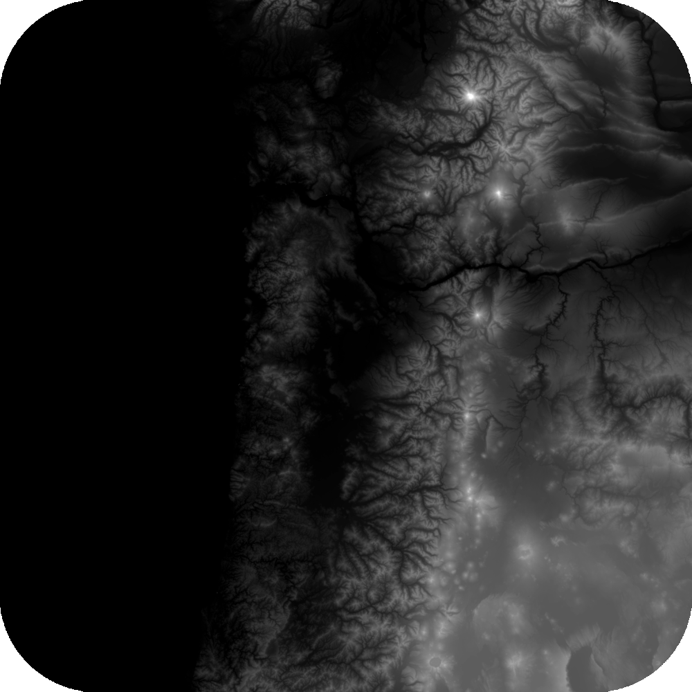
A heightmap is just a grayscale picture where brightness stands in for elevation. Black is the lowest point in the region, white is the highest, and every gray in between is somewhere in the middle. This one is 1000×1000 pixels.
The image also has an alpha channel with rounded, transparent corners. That transparency does double duty later: it tells the renderer which pixels should be invisible, and it tells the elevation code to treat those pixels as sea level so the edges of the model stay flat instead of spiking.
From Pixels to a Surface
When the page loads, the browser draws the PNG onto a hidden 2D canvas and reads the raw pixel data back out. That gives us a big array of red, green, blue and alpha values, one set per pixel, which is all we need to sample elevation at any point on the map.
const img = new Image();
img.crossOrigin = 'anonymous';
img.src = heightmapUrl;

img.onload = () => {
  const canvas = document.createElement('canvas');
  canvas.width = img.width;
  canvas.height = img.height;
  const ctx = canvas.getContext('2d');
  ctx.drawImage(img, 0, 0);

  // Flat Uint8ClampedArray: [r, g, b, a, r, g, b, a, ...]
  const { data } = ctx.getImageData(0, 0, img.width, img.height);
  heightmapRef.current = { data, width: img.width, height: img.height };
};
Anything on the CPU side that needs the height at an arbitrary point (the contour lines, for example) uses a small sampler that takes a UV coordinate in the 0–1 range, reads the red channel of the four surrounding pixels, and blends them. Transparent pixels report an elevation of zero.
export function sampleHeightmap(u, v, data, width, height) {
  const x = u * (width - 1);
  const y = v * (height - 1);
  const x0 = Math.floor(x), x1 = Math.min(x0 + 1, width - 1);
  const y0 = Math.floor(y), y1 = Math.min(y0 + 1, height - 1);
  const fx = x - x0, fy = y - y0;

  const getPixel = (px, py) => {
    const idx = (py * width + px) * 4;
    if (data[idx + 3] / 255 < 0.1) return 0;   // transparent → sea level
    return data[idx] / 255;                      // red channel = height
  };

  // Bilinear interpolation between the four nearest pixels
  const top    = getPixel(x0, y0) * (1 - fx) + getPixel(x1, y0) * fx;
  const bottom = getPixel(x0, y1) * (1 - fx) + getPixel(x1, y1) * fx;
  return top * (1 - fy) + bottom * fy;
}
The 3D surface itself starts as a completely flat square plane, 100 units on a side, subdivided into a grid. The number of subdivisions is the "Segments" setting in the control panel. A 250×250 grid is about 62,000 vertices, while the full 1000×1000 grid is a million. The presets are chosen so the vertex grid lines up cleanly with the pixel grid of the heightmap (1:1, 2:1, 4:1 and so on). Going finer than one vertex per pixel would just add geometry with no new detail to show.
Rather than pick one resolution for everyone, the page runs a quick GPU detection when it loads and picks a default: the highest preset for desktop-class GPUs, the lowest for phones, and the middle for everything in between. You can always override it from the panel and hit "Regenerate Terrain."
Pushing the Vertices Up
The flat plane becomes mountains through a displacement map. The heightmap is converted into a texture and handed to the material, and the GPU moves each vertex up along its normal by an amount proportional to how bright the texture is at that spot. Because this happens on the graphics card in the vertex shader, even the million-vertex mesh displaces essentially for free, and changing the "Elevation Scale" slider only changes a single multiplier.
The displacement texture is built once, right after the pixels are read. It's just the red channel copied into a fresh canvas, with anything under the transparent corners zeroed out, then wrapped in a CanvasTexture.
const dispImageData = dispCtx.createImageData(width, height);

for (let i = 0; i < data.length; i += 4) {
  const alpha = data[i + 3];
  const value = alpha < 10 ? 0 : data[i];     // red channel, or 0 if transparent
  dispImageData.data[i]     = value;
  dispImageData.data[i + 1] = value;
  dispImageData.data[i + 2] = value;
  dispImageData.data[i + 3] = 255;
}

dispCtx.putImageData(dispImageData, 0, 0);
const dispTex = new THREE.CanvasTexture(dispCanvas);
dispTex.colorSpace = THREE.LinearSRGBColorSpace;  // it's data, not colour
That last line matters more than it looks. Three.js treats textures marked sRGB as colour and has the GPU run an sRGB→linear decode when sampling. If the height texture gets tagged that way, every height h becomes roughly h2.2: the lowlands flatten out and only the near-white volcano peaks survive. Some React Three Fiber versions auto-tag every texture prop as sRGB, so in the blog version the data textures are assigned to the material imperatively to keep that from happening.
From there, the material does all the work:
<meshStandardMaterial
  map={colorTexture}
  displacementScale={heightmapScale * 30}
  flatShading={flatShading}
  transparent
  alphaTest={0.1}
/>
One wrinkle: at the rounded corners, the elevation drops from mountain to zero within a pixel, which would produce sheer vertical walls along the border. To avoid that, before the displacement texture is built the code measures how far each pixel is from the nearest transparent pixel and smoothly fades elevation to zero over the last thirty pixels. The result is a soft taper to a flat edge.
const FEATHER_PX = 30;

for (let i = 0; i < pixelCount; i++) {
  const d = edgeDist[i];                    // pixels to nearest transparent pixel
  if (d <= 0 || d >= FEATHER_PX) continue;  // fully inside or fully outside

  const t = d / FEATHER_PX;
  const factor = t * t * (3 - 2 * t);       // smoothstep: 0 at edge → 1 at 30px
  const idx = i * 4;
  const faded = Math.round(dispImageData.data[idx] * factor);
  dispImageData.data[idx] = dispImageData.data[idx + 1] = dispImageData.data[idx + 2] = faded;
}
Coloring the Terrain
The color you see is also derived from the heightmap. There are three shader modes in the panel:
- Terrain Bands (the default) assigns colors to elevation ranges the way a physical relief map does. Slate blue for water, sandy beige for shoreline, greens for lowlands and forest, browns and grays for rocky slopes, white for snow. The band thresholds scale with the elevation slider so the snow line stays in a sensible place when you exaggerate the height.
- Elevation Gradient normalizes elevation across the whole map and runs it through a smooth blue → green → yellow → orange → red gradient, which is handy for reading relative height at a glance.
- Standard ignores elevation and uses a single flat color, which flips between white and black with the site theme. It is the most useful mode for looking at the wireframe.
In the two colored modes the color is baked into a texture by walking over every pixel of the heightmap once, so switching shaders or changing the elevation scale regenerates a 1000×1000 texture rather than touching any geometry. The terrain bands are nothing more than a lookup table keyed on elevation in world units:
const scaleRatio = heightmapScale / 0.15;   // bands were tuned at scale 0.15

const bands = [
  { max: 0,                r: 84,  g: 110, b: 122 },  // water
  { max: 0.1 * scaleRatio, r: 188, g: 170, b: 154 },  // shore
  { max: 0.2 * scaleRatio, r: 168, g: 184, b: 140 },  // lowland
  { max: 0.6 * scaleRatio, r: 141, g: 155, b: 107 },  // grassland
  { max: 1.0 * scaleRatio, r: 107, g: 127, b: 92  },  // low forest
  { max: 1.5 * scaleRatio, r: 85,  g: 107, b: 80  },  // forest
  { max: 1.8 * scaleRatio, r: 139, g: 115, b: 85  },  // highland
  { max: 2.5 * scaleRatio, r: 167, g: 149, b: 132 },  // mountain
  { max: 3.2 * scaleRatio, r: 201, g: 188, b: 179 },  // high mountain
  { max: Infinity,         r: 255, g: 255, b: 255 },  // snow
];

for (let i = 0; i < data.length; i += 4) {
  const rawHeight = data[i + 3] < 26 ? 0 : data[i] / 255;
  const z = rawHeight * heightmapScale * 30;          // same formula the GPU uses

  const band = bands.find(b => z <= b.max);
  out[i] = band.r; out[i + 1] = band.g; out[i + 2] = band.b; out[i + 3] = 255;
}
Lighting and Shading
Three lights illuminate the scene: a soft ambient light, a strong warm "sun" from the upper right, and a faint blue fill light from the opposite side to keep the shadowed slopes from going completely black.
For lighting to look right, the renderer needs to know which way the surface faces at every point. Since the displacement happens on the GPU, the mesh's original flat normals are useless. The fix is a normal map: another texture, computed from the heightmap by comparing each pixel to its neighbors to figure out the slope in each direction. With "Flat Shading" enabled (the default) the renderer instead computes one normal per triangle, which gives the faceted, low-poly look. Turning it off switches to the smooth normal map.
// strength converts a per-pixel height difference into a world-space slope
const strength = heightmapScale * 30 * (width / 100);

for (let py = 0; py < height; py++) {
  for (let px = 0; px < width; px++) {
    // Central differences: slope in X and Y from the neighbouring pixels
    const dx = (getHeight(px + 1, py) - getHeight(px - 1, py)) * 0.5 * strength;
    const dy = (getHeight(px, py + 1) - getHeight(px, py - 1)) * 0.5 * strength;
    const len = Math.sqrt(dx * dx + dy * dy + 1);

    // Pack the unit normal (-1..1) into RGB (0..255)
    const idx = (py * width + px) * 4;
    out[idx]     = Math.round((-dx / len * 0.5 + 0.5) * 255);
    out[idx + 1] = Math.round(( dy / len * 0.5 + 0.5) * 255);
    out[idx + 2] = Math.round(( 1  / len * 0.5 + 0.5) * 255);
    out[idx + 3] = 255;
  }
}
Fog is a plain distance fade to the background color. The "Fog Near" and "Fog Far" sliders control where the fade starts and where the terrain fully disappears, and the fog color is kept in sync with the light or dark site theme so the horizon dissolves cleanly.
Contour Lines
Toggling contours draws topographic lines across the surface at a fixed elevation interval. This is the one feature that can't ride along on the GPU displacement, because finding where a contour crosses the surface requires knowing the real 3D position of every vertex.
So when contours are on, the code builds a second, CPU-displaced copy of the grid by sampling the heightmap for each vertex. It then runs a marching squares pass: for every elevation level and every grid cell, it checks which edges of the cell straddle that elevation, interpolates the exact crossing points, and connects them with a short line segment. The segments are nudged a hair above the surface so they don't flicker against the terrain. On the highest mesh resolution this is a noticeable chunk of work, which is why it's off by default.
// For one grid cell with corners c0..c3 and one contour elevation
const edges = [[c0, c1], [c1, c2], [c2, c3], [c3, c0]];
const intersections = [];

edges.forEach(([p1, p2]) => {
  const straddles = (p1.z <= elevation && p2.z >= elevation) ||
                    (p1.z >= elevation && p2.z <= elevation);
  if (!straddles || Math.abs(p2.z - p1.z) < 0.001) return;

  // Where along the edge does the surface cross this elevation?
  const t = (elevation - p1.z) / (p2.z - p1.z);
  intersections.push({
    x: p1.x + t * (p2.x - p1.x),
    y: p1.y + t * (p2.y - p1.y),
    z: elevation + 0.05,          // lift slightly to avoid z-fighting
  });
});

if (intersections.length >= 2) {
  linePoints.push(...xyz(intersections[0]), ...xyz(intersections[1]));
}
The Camera
You can orbit, pan and zoom freely with the mouse, with limits so you can't drop below the ground or fly off into the fog.
When nobody is touching it, an automatic camera takes over and runs through a short list of cinematic shots: a slow orbit, a low flyover, a pull back, a climb, an overhead view, and a look south from the north edge. Each shot is just a start and end position plus a target point and a duration, and the camera interpolates between them. When one shot hands off to the next, the position is eased over about a second and a half so there's no hard cut, and the look-at target trails slightly behind so the horizon doesn't snap. Grabbing the camera pauses the tour; resuming it blends smoothly from wherever you left it back into the sequence.
Each shot is declared as data. A shot only needs to define where it ends, because it starts wherever the previous shot finished:
const KEYFRAMES = [
  {
    name: 'Slow Orbit',
    duration: 15000,
    start: { position: [-35.94, 31.69, -19.89], target: [0, 0, 0] },
    end:   { position: [2.31, 26.36, 72.09],    target: [1.11, -11.3, 4.91] },
  },
  { name: 'Flyover',  duration: 15000, end: { position: [8.53, 19.29, 14.88],  target: [7.97, -0.14, -7.97] } },
  { name: 'Backup',   duration: 12000, end: { position: [81.02, 36.7, 3.69],   target: [0.23, -0.67, 2.3] } },
  { name: 'Move up',  duration: 8000,  end: { position: [69.96, 70.95, -2.32], target: [21.6, -1.84, -2.3] } },
  { name: 'Overhead', duration: 10000, end: { position: [23.23, 97.54, -1.98], target: [6.72, -0.73, -1.93] } },
  { name: 'North Looking South', duration: 10000, end: { position: [-7.75, 54.25, -75.45], target: [-0.78, -5.61, -4.98] } },
];
Every frame, the camera controller asks the current shot where the camera should be for the elapsed time, then eases toward it if a transition is in progress:
useFrame(() => {
  if (!autoRotateRef.current) return;

  const elapsed = Date.now() - shotStartTimeRef.current;
  const shot = CAMERA_SHOTS[shotIndexRef.current];
  const { position, target } = shot.compute(elapsed / 1000);

  // Blend from wherever we were into the new shot over 1.5s
  if (transitionProgressRef.current < 1) {
    transitionProgressRef.current = Math.min(1, elapsed / TRANSITION_DURATION);
    camera.position.lerpVectors(prevPositionRef.current, position, easeInOut(transitionProgressRef.current));
  } else {
    camera.position.copy(position);
  }

  // The look-at target trails a little so the horizon never snaps
  currentTargetRef.current.lerp(target, 0.06);
  camera.lookAt(currentTargetRef.current);
});
The stats button in the bottom left opens a small panel showing the current shot, frame rate, vertex count, camera coordinates, and what the GPU detection decided about your machine.
Performance Notes
A few things keep this smooth on modest hardware:
- Displacement, lighting and coloring are all texture-based, so changing shaders, fog, opacity or the elevation slider never rebuilds the mesh.
- The mesh is only regenerated when you explicitly click "Regenerate Terrain," so you can change several settings before paying the cost once.
- The device pixel ratio is capped at 2, since rendering at 3× on high-DPI phones burns GPU time for no visible gain.
- The canvas is kept invisible until the first frame with the displacement texture has actually been drawn, which avoids a flash of flat gray plane while textures load.
The same component is what powers the home page of Cascadia Code, where it runs full-screen behind the site header.