Ground Control 40
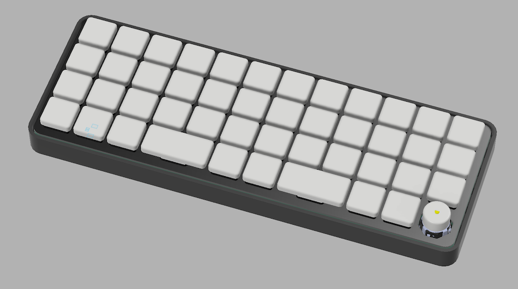
The Final Build
This is a build log, but let's start with the final product so you can see what we are building up to.
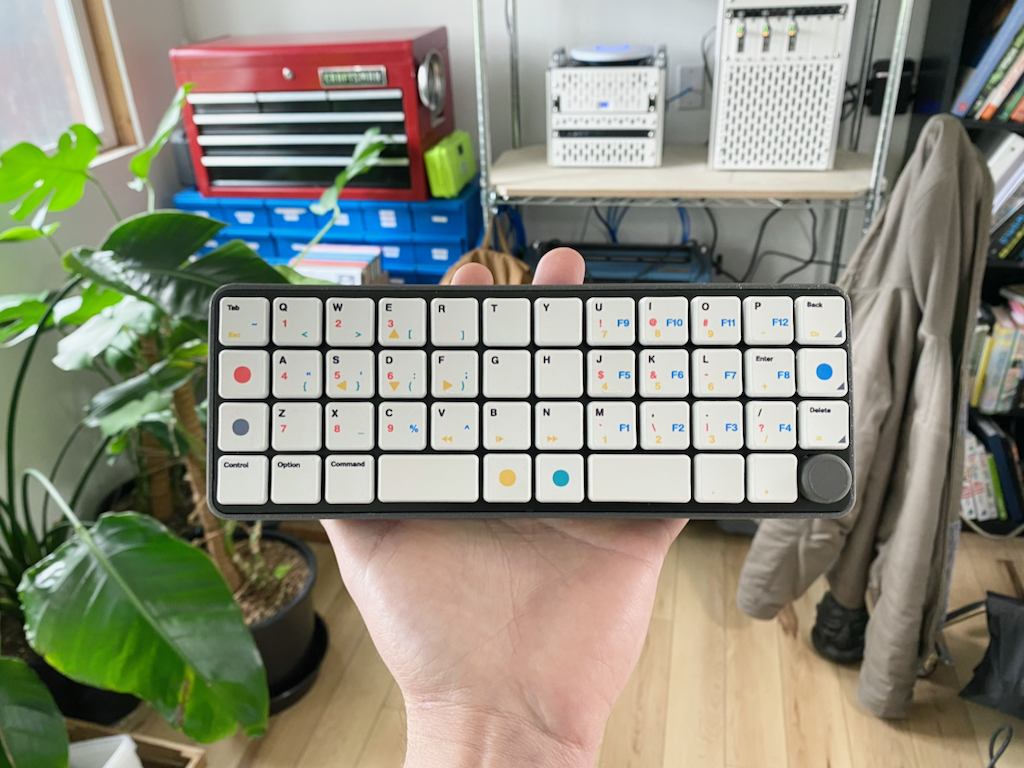
The GC40 (Ground Control 40) is a custom 40% Ortholinear keyboard with the following features:
- Wireless (Bluetooth & Wifi)
- Wireless charging
- 128x128 OLED Display
- ESP32-S3 Microcontroller
- CFX profile Keycaps
- Choc V1 low profile mechanical switches
- Rotary Encoder + Multidirectional Switch (in one)
- Hotswap Sockets
- Fully custom PCBs
- Fully custom keycap dye sublimation
- Fully custom firmware
- Travel Case
- Open Source dev board
This has been an intermittent project for the last 3 years which I'm excited to finally share. I believe it is completely unique in many of its design features.
Engineering
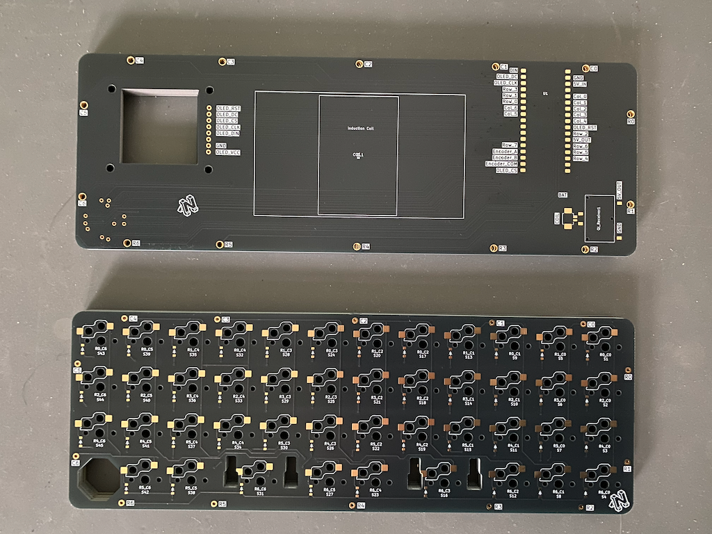
V2 PCBs freshly unpacked.
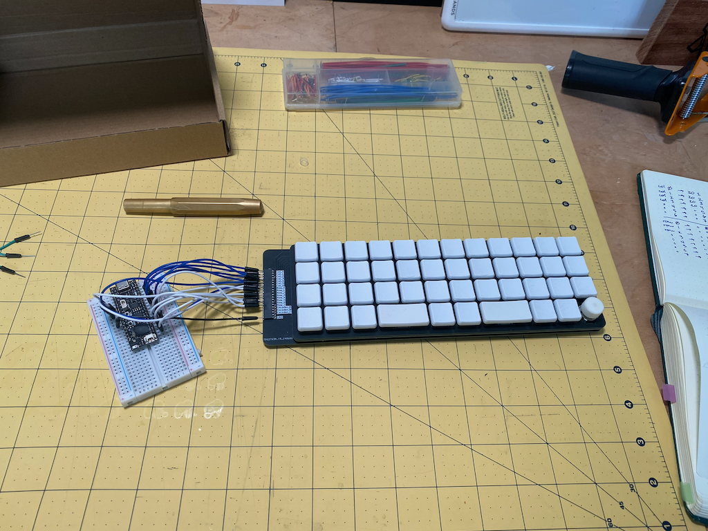
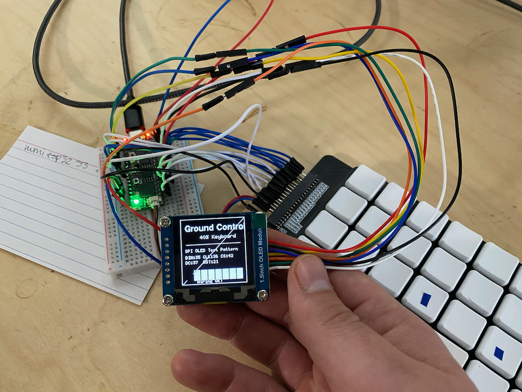
Dev board breadboarded up to microcontroller for first time.
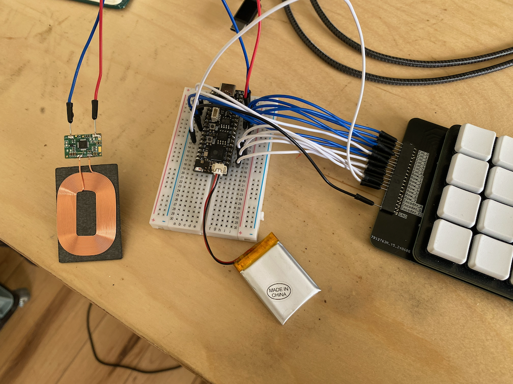
Wireless Qi protocol induction coil and battery functional
Pixels on screen.
My main design tools:
- Autodesk Fusion (3D Modeling)
- Kicad (PCB Design)
- Adobe Illustrator
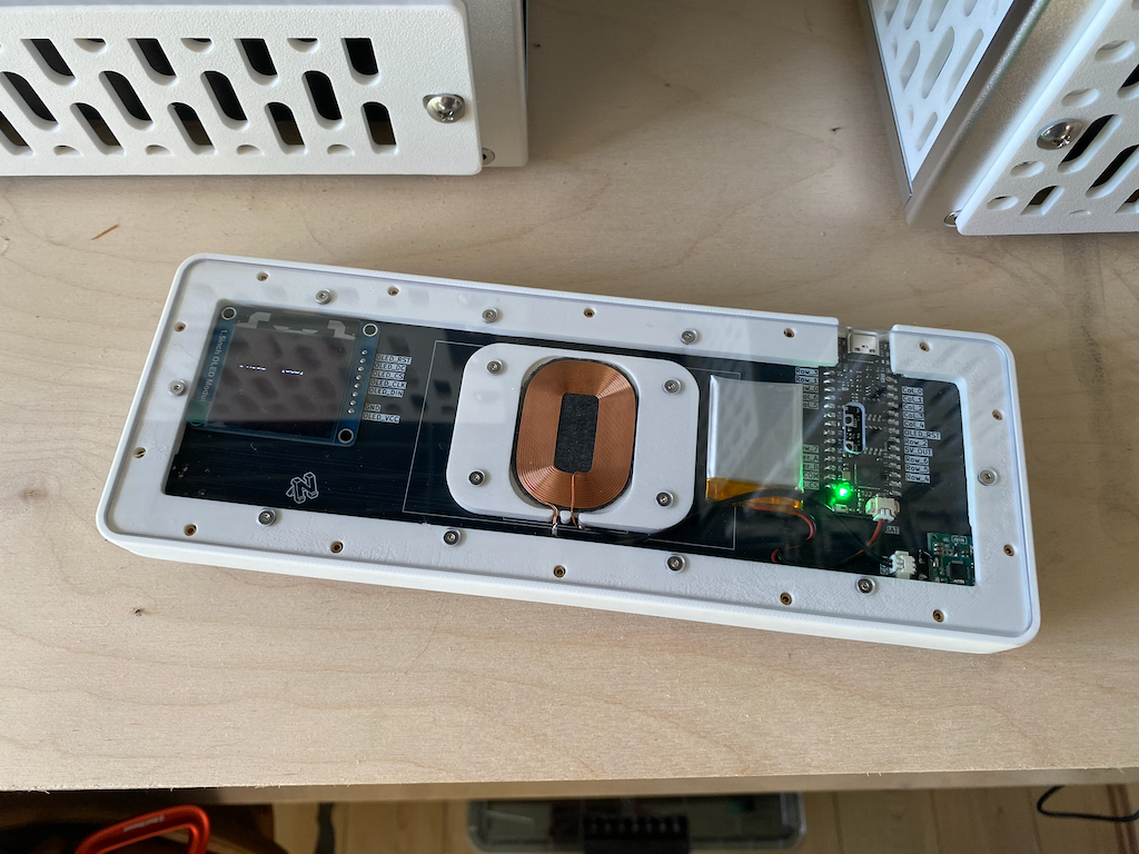
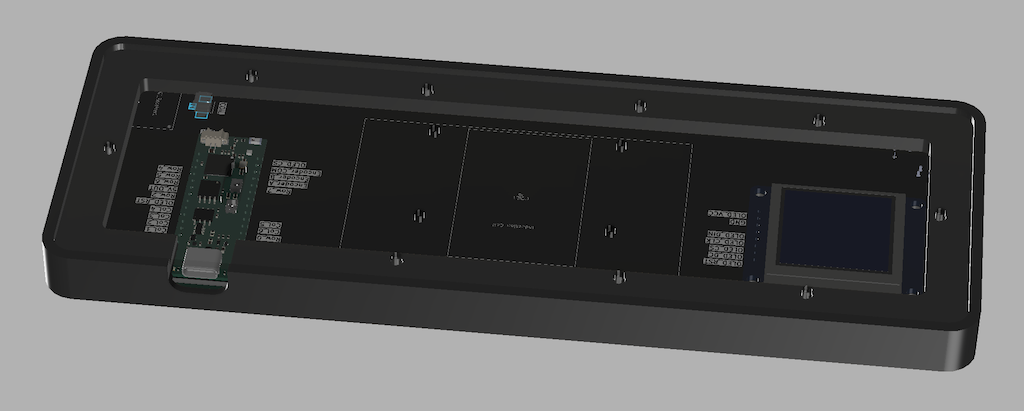
In this project I have three PCB layers.
- Mounting Plate: Top layer. The switches and stabilizers snap into this plate. No electrical components on this layer.
- Switch Plate: Middle layer. Where all the hotswap sockets and transistors for the switch matrix live.
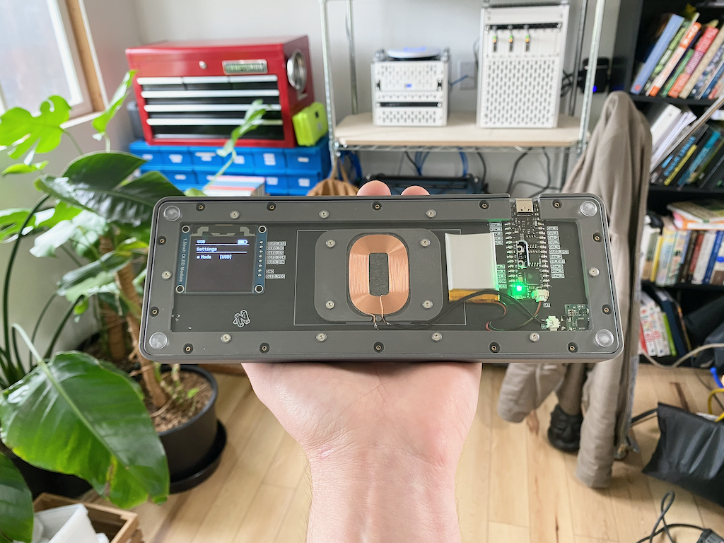
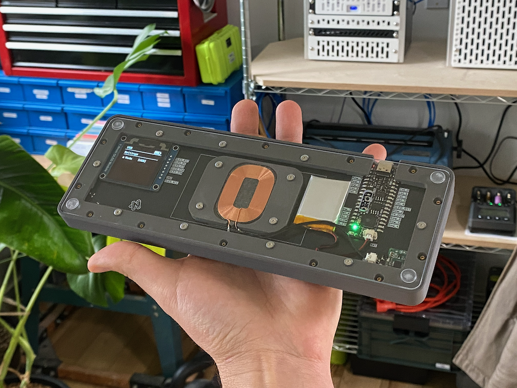
- Main Plate: Bottom layer. Where the microcontroller, multi-switch, OLED & wireless charging components live.
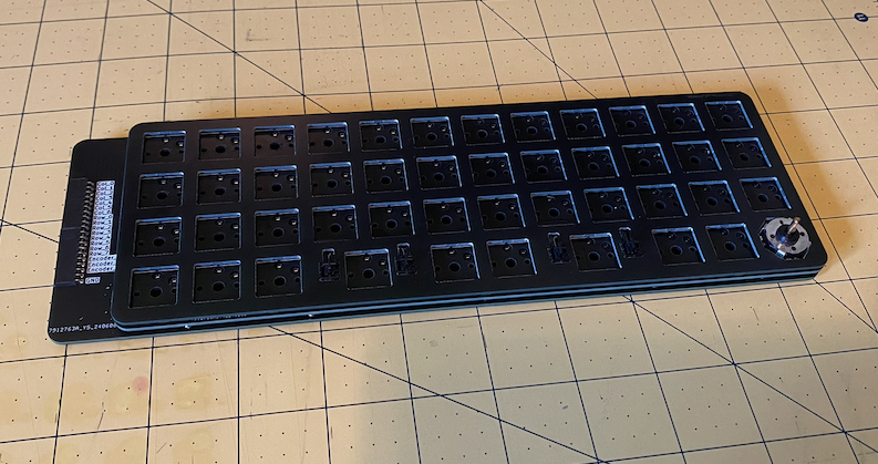
You can see that the Main Plate in the picture above has extra material and a row of connectors on the left hand side. This is the Dev Board version of the Main Plate, which I made before the final V2 version. I did this because I didn't know at the time if my preferred microcontroller would even work, and how to wire up all the components correctly. This Dev Board version allows the switch matrix to be wired up to a breadboard for easy testing with any components you want.
As I learned, there is sort of a flow to the process of engineering one of these things and I'll explain that here.
- Initial layout and form factor in AutoDesk Fusion
- Export Fusion sketches to Kicad
- Schematics and PCB design in Kicad
- Export PCB
.stepfiles back into Fusion to design case etc.
Master Sketch
The first thing you have to do is decide what keycap profile you are going to use, and the layout. I'll tell you why.
The keycaps are one of the pieces that you essentially must buy off the shelf, and their dimensions then define the footprint for the entire project.
Once you know what keycap profile you want you will be able to measure them to get precise x/y dimensions for the keycaps. They aren't all the same! The most common profiles are actually rectangular while something like CFX for example is square.
Once you have that measurement you know how far apart you need to space your switches. Now you can design the mounting plate in your CAD software of choice. The thickness of the mounting plate will be defined by the switches you are using. You also need to create mounting holes for stabilizers for any keys you have that are larger than 1.5u.
After the keycap profile and layout have been determined, designing the mounting plate is just a logical process with few if any creative decisions.
In Autodesk Fusion, you create a sketch, then export a DXF file. Those DXF files can then be imported into Kicad to be used as cut and layout lines for the PCB. Especially useful for example if you have multiple PCB's that will be stacked on top of each other and they all need to line up perfectly.
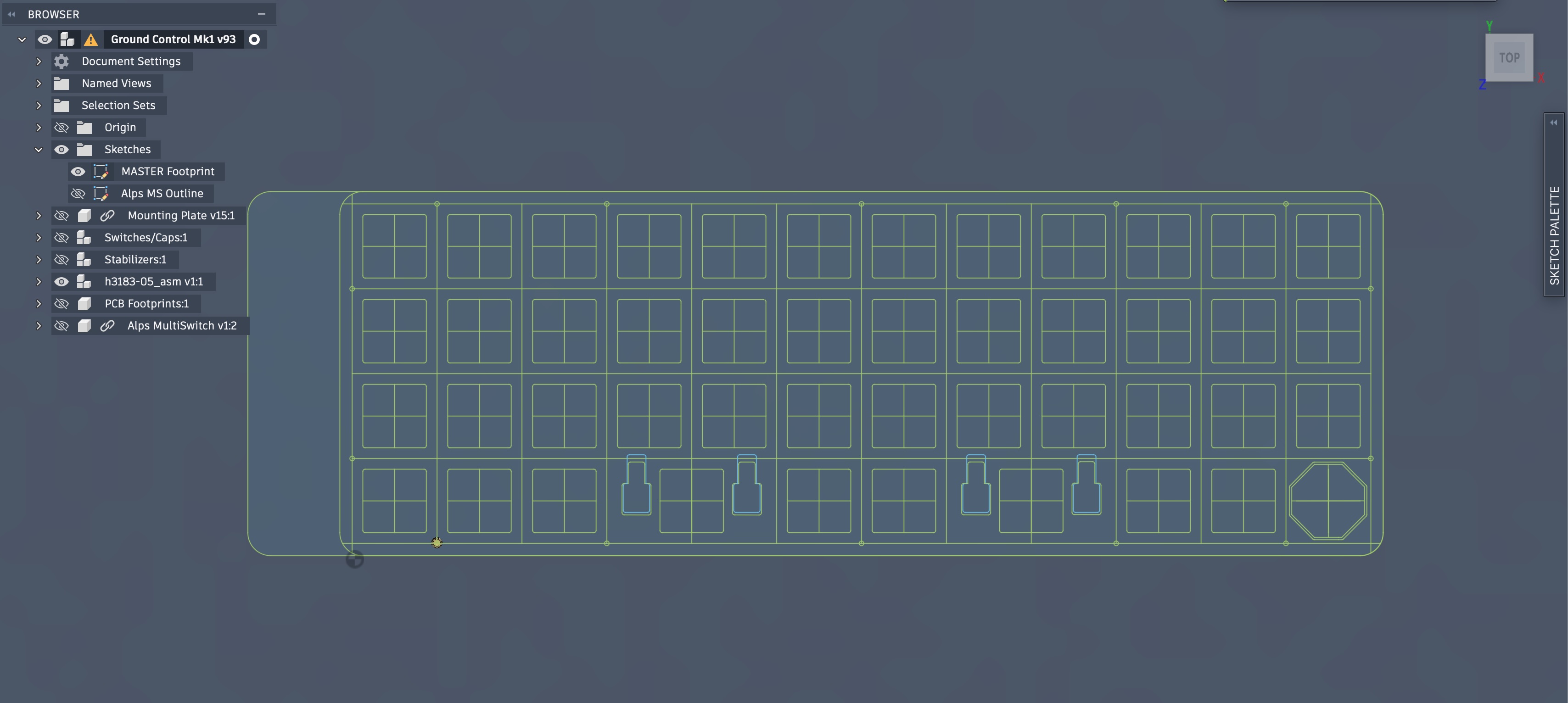
This is the MASTER Sketch for my keyboard created in Fusion. With this sketch I can precisely align all the switches. I have defined my mounting plate, as well as the outline for all three of my PCB's. This sketch can be imported directly to Kicad to serve as the source of truth for all your PCB dimensions.
Folded Multi-PCB Matrix
The next step is to head into Kicad and create your electrical schematic (or schematics in my case).
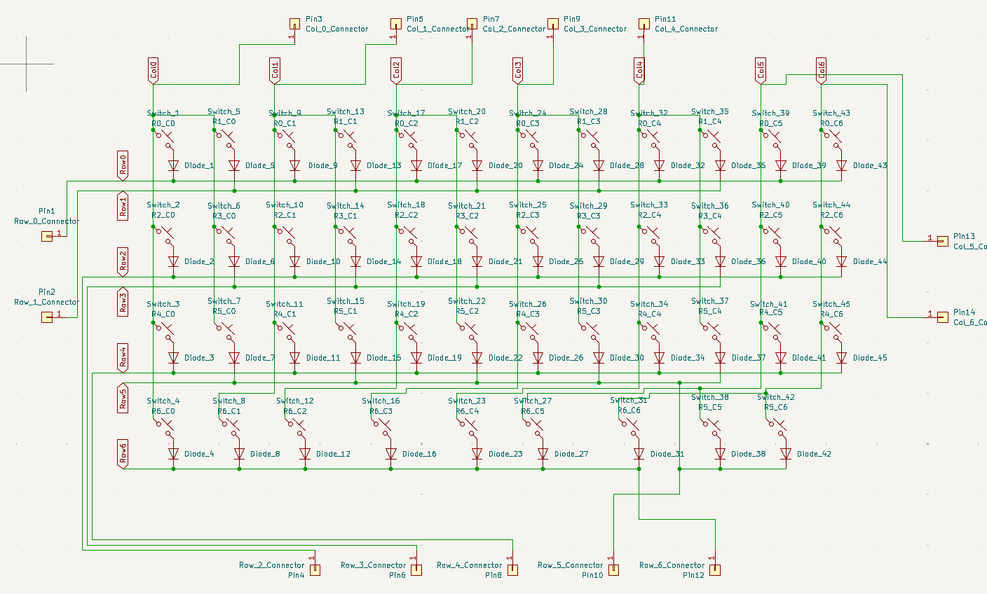
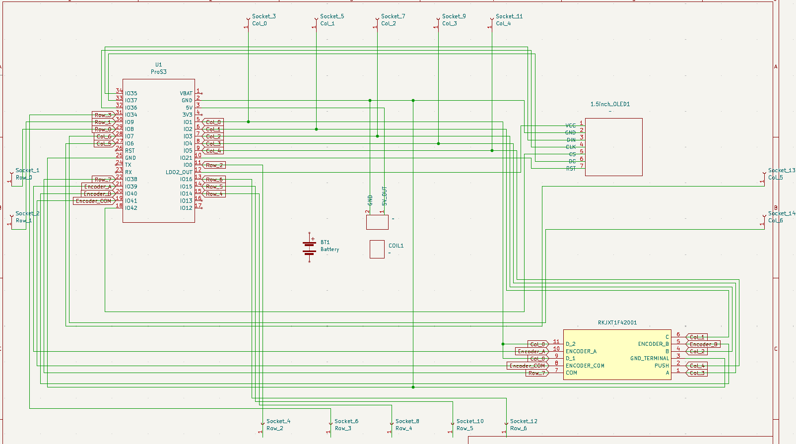
The schematic exists just to define the electrical circuit without taking into account the real physical layout (how large each component is, where exactly it is positioned etc). The physical layout is handled in the PCB editor afterwards.
This board uses something called a "Folded" or "Duplex" matrix. We do this to use the least amount of IO pins on the microcontroller as possible so that we have more available for peripherals like the OLED screen later. This article does a good job of explaining what it is: The Duplex Matrix
In short, it's not maximally efficient to have an electrical row and column for each physical row and column on the board. You want the electrical switch matrix to be as close to square as possible to get the most switches wired up using the least amount of IO pins possible.
To make this a bit more complicated, not all of my switches are actually on the same PCB...
Alps MultiSwitch
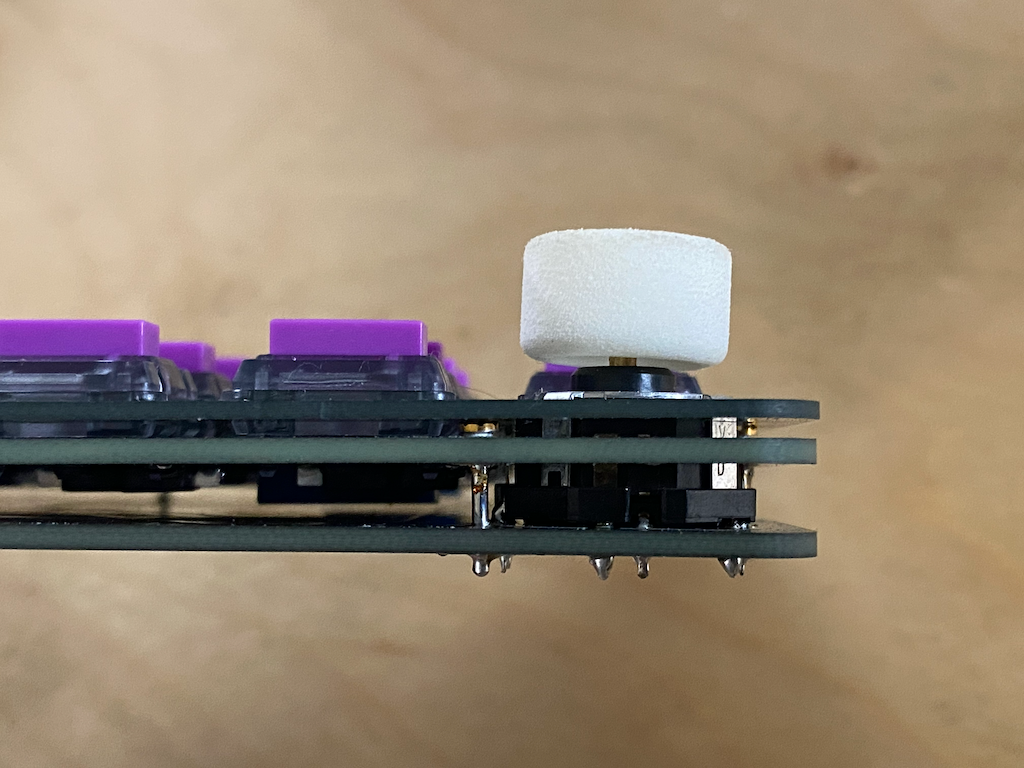
The Alps RKJXT1F42001 is both a rotary encoder (it spins) and 5-direction stick (Up,Down,Left,Right,Push) in one. One of the challenges of integrating this switch however is that it is about 2.5x the height of all the other switches on the keyboard. To resolve this I placed it on the Main Board instead of the Switch Board.
The rotary encoder functionality requires its own pins, but the directional functionality actually gets integrated into the switch matrix.
For that reason the folded switch matrix actually spans multiple PCB's. That was a real brain twister.
PCB Footprints
After you have the schematics complete you switch to PCB layout mode in Kicad, where you integrate the Master Sketch from Fusion and your schematic together.
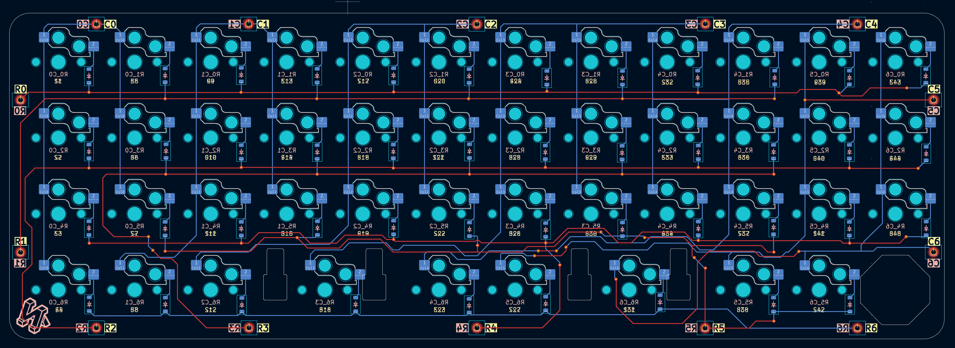
One of the great things about this three layer design is that the "Bottom" layer or Main Plate as I call it is the only one that needs to be modified when moving from the Dev Board version to the V2 or final version. The Mounting Plate and Switch Plate can remain virtually unchanged. In fact you could create several iterations all using different microcontrollers and peripherals without needing to make modifications to 2/3rds of the PCB's. This modular design lends itself very well to experimentation.
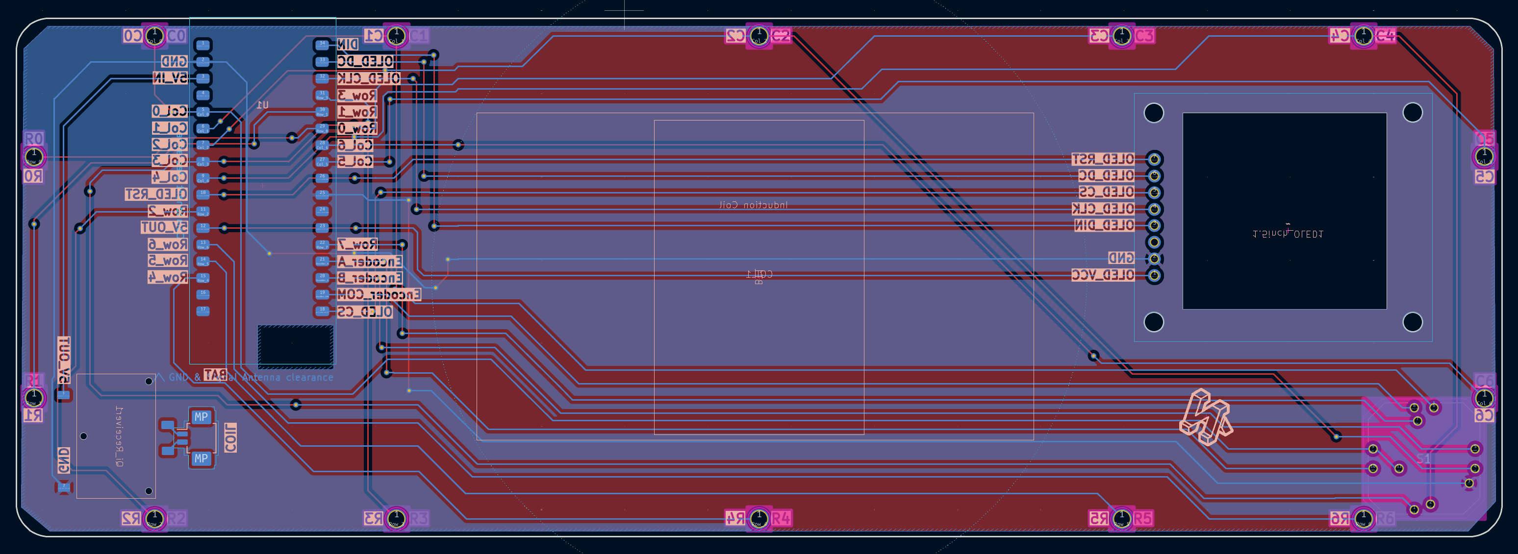
Wireless charging
Adding wireless charging was another layer of complexity. The copper coil you see here is an induction coil, which then leads to its own little chip on the Main Plate.
That chip is what implements the Qi Wireless Charging standard. In a nutshell it just makes it so that it passes 5 volts to the microcontroller, or nothing. There is no in between.
The most difficult part of integrating the induction coil is that it has a very short operational distance between it and the charging coil, so it needed to be placed as near the bottom as possible. Additionally, it looks really cool so now I have to make the back clear.
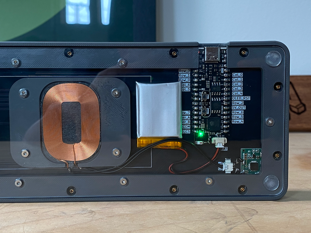
I ended up using a custom cut 2mm thick polycarbonate panel, that I then countersunk using a drill press with a 90 degree bit which is the angle required for the M2 screws. The charging coil has it's own 3D printed mount which I call the Coil Block. That mount and the case have heat-set threaded inserts to sandwich everything together.
Additionally the battery and charging coil are both attached with 2 channel Molex Picoblades so that they can be swapped out easily without further soldering.
OLED
I've programmed in a 3-key combination that toggles the power on the OLED so it's not always on wasting battery. The settings menu can be controlled using the Alps MultiSwitch like a little joystick.
It might seem like an unnecessary complication to add the screen, but the ESP32 S3 provides so many potential functionalities that you basically have to include one to accommodate all the potential use cases.
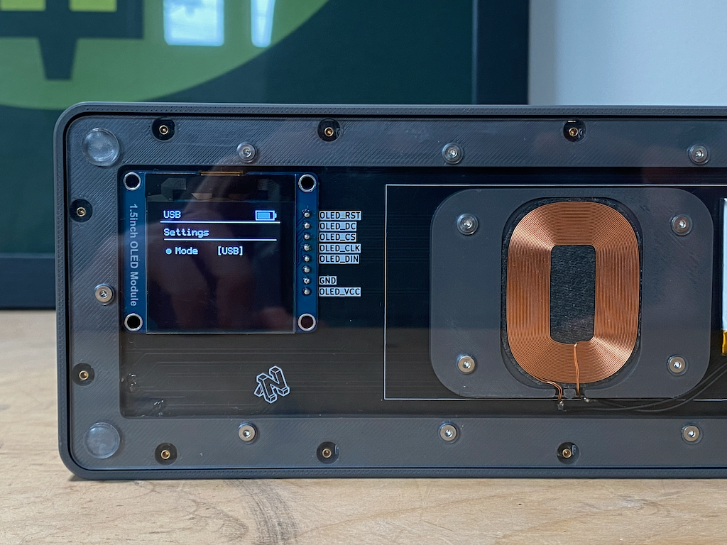
Plus it looks cool.
Firmware
There is no community firmware like QMK that exists for the ESP32, or at least none that can handle all of the use cases that the peripherals on this board require. Believe me, I looked. Because of that I ended up writing a custom firmware completely from scratch, in Arduino. Ouch. Despite the immense amount of engineering involved in the physical components on this board, this was actually about half of the project, and not the fun half.
I did get to learn a lot about the USB HID Specification which is the protocol that defines how computers expect to receive data from keyboards.
One of the interesting things I learned is that there is no keycode for a lot of the special characters like !. To tell the computer you want to type an exclamation mark you actually send SHIFT + 1. Which is why on pretty much every keyboard everywhere the number one and exclamation mark are on the same key. Separating those two and all the other special characters like I wanted to was a unique challenge.
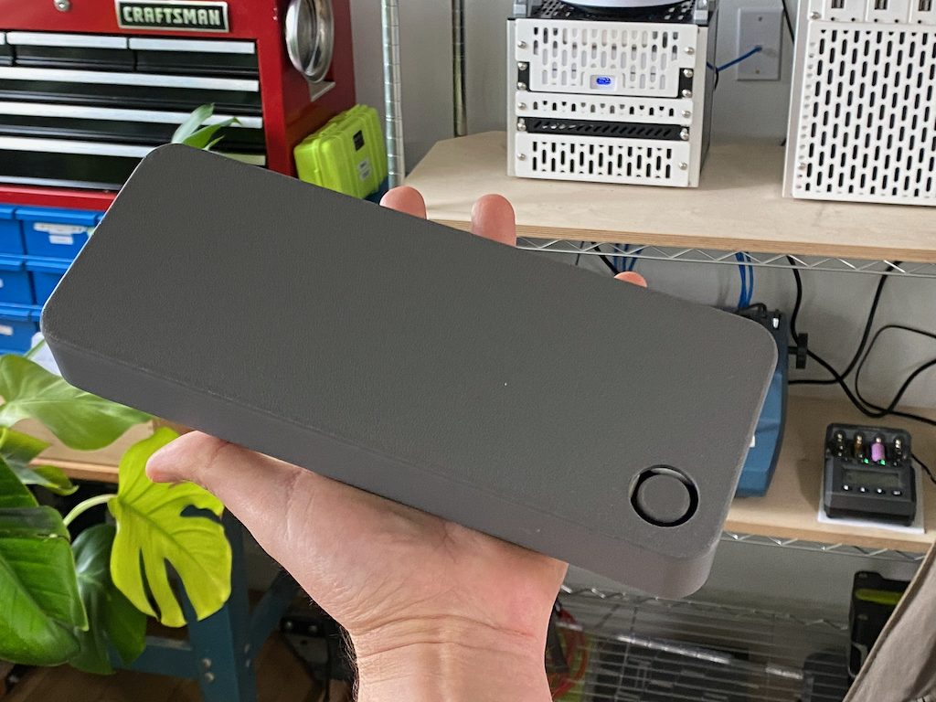
Case
Once the PCB layouts in Kicad are complete you will have a 3D model that includes all the soldered on components which you can then export together into a .step file. You can then arrange those 3D models together and design your Case and other required parts around them. For me that was the case, coil mounting block, polycarbonate panel, rotary encoder knob and travel case.
I ran into some of the typical 3D printing problems like low quality overhangs, shrink lines and lifting but was able to work through them to get passable prints. The final case is not perfect, but it's pretty close.
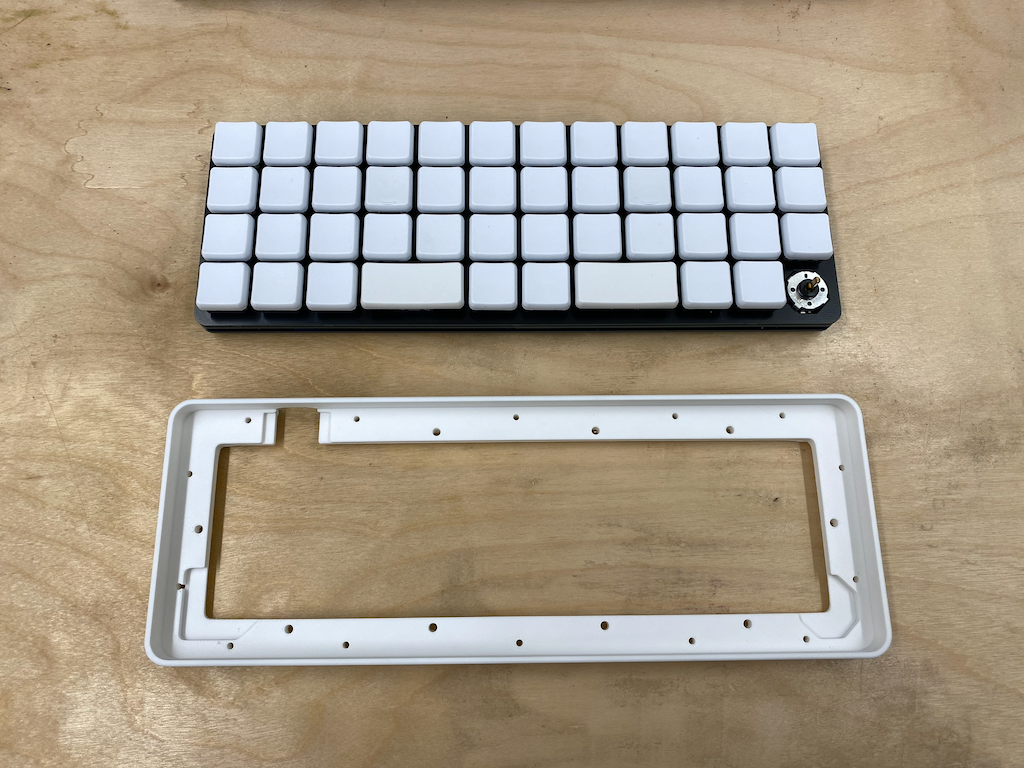
The main case is a solid piece that the Main Plate snaps into a pressure fit position. Once inside you have to destroy the case to remove it (if you don't want to put stress on the PCB's). Which isn't really an issue since I can 3D print as many as I want.
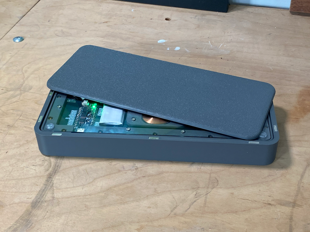
Travel Case
I designed a travel case with a magnetic lid so that I can chuck the board in my backpack for travel. The entire board inside the travel case is still smaller than a standard 60% board, which makes taking it on the go a breeze.
The lid attaches using magnetic inserts, and there is a silicone mat attached to the lid so that the polycarbonate panel doesn't get scratched in transport.
Dye Sublimation
There is definitely no off the shelf keycap set for this keymap, especially not on a CFX profile keycap, so we are making our own.
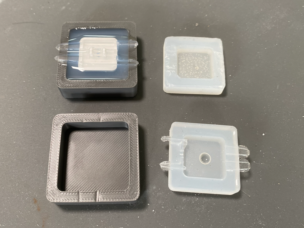
I started by 3D printing a little container to pour a custom silicone mold for this keycap.
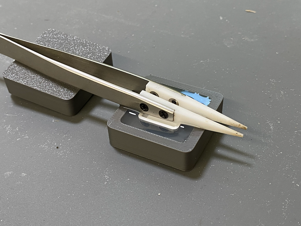
We do this because we need to have precisely and evenly distribute heat and pressure across the entire curved surface of the keycap. My initial attempt had an air bubble in the middle because of the convex shape of the cap face. I solved that by drilling a hole in the middle of the cap. Round two was successful.
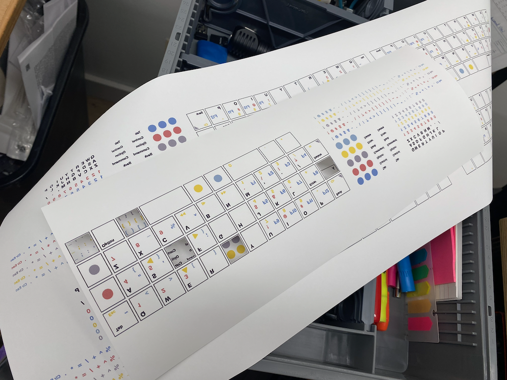
You have to print your keycap design at 100% scale on dye sublimation paper, cut out the individual keys and tape them to the face of the keycaps using heat tape.
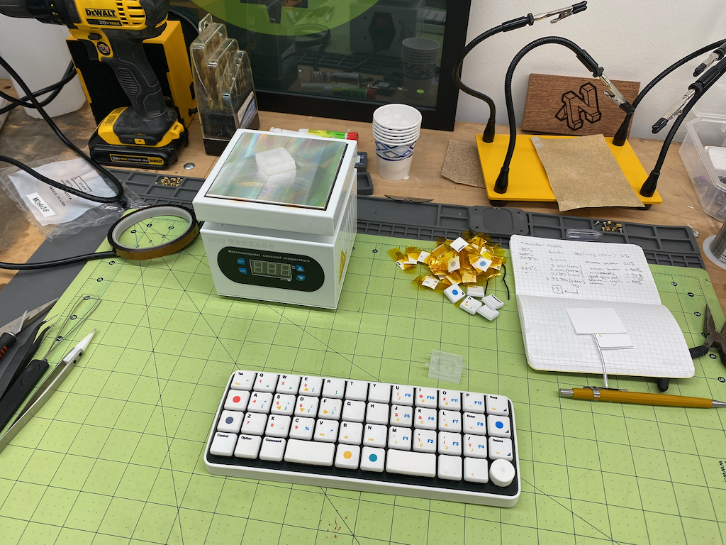
Then you insert the keycap face down onto a resoldering plate to precisely control the temperature, and apply moderate pressure for a set amount of time. This is a long and tedious process.
The exact temperature and time will vary based on your application, but you do have to be careful because the temperature required to vaporize the dye sublimation ink and the deformation temperature of PBT are not that far appart. You'll want to have some spare caps and prints to experiment until you find the right combination.
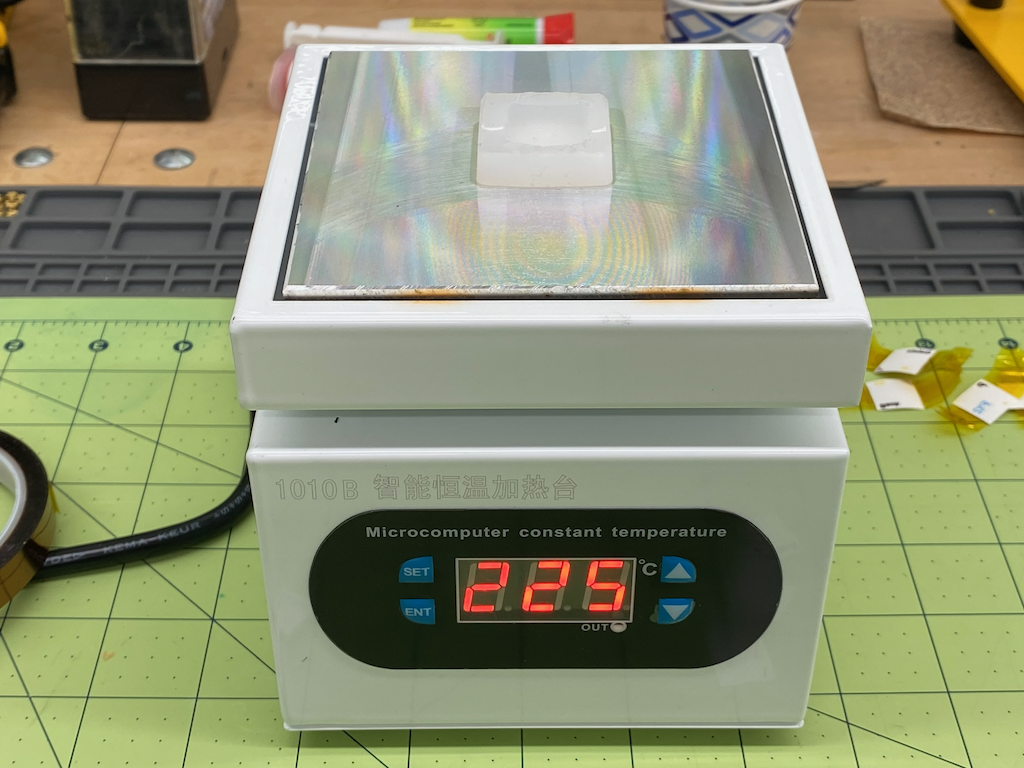
For me it was 225 degrees celcius for three minutes.
Concept and Research
Why would someone go to all this trouble? That is a reasonable question. Let me explain how I arrived at the concept for this board.
40% Form Factor
I've always been fascinated with the smaller form factor keyboards. They look cool, and in theory they are incredibly efficient. In practice I did not find that to be the case. After using a 60% board for many years I decided to dip my toes into the world of 40% boards. This was about 10 years ago and options were limited. You could get a Minivan or a Vortex Core. The Minivans were only available through group buys, which were always sold out, and cost twice as much.
I bought a Core.
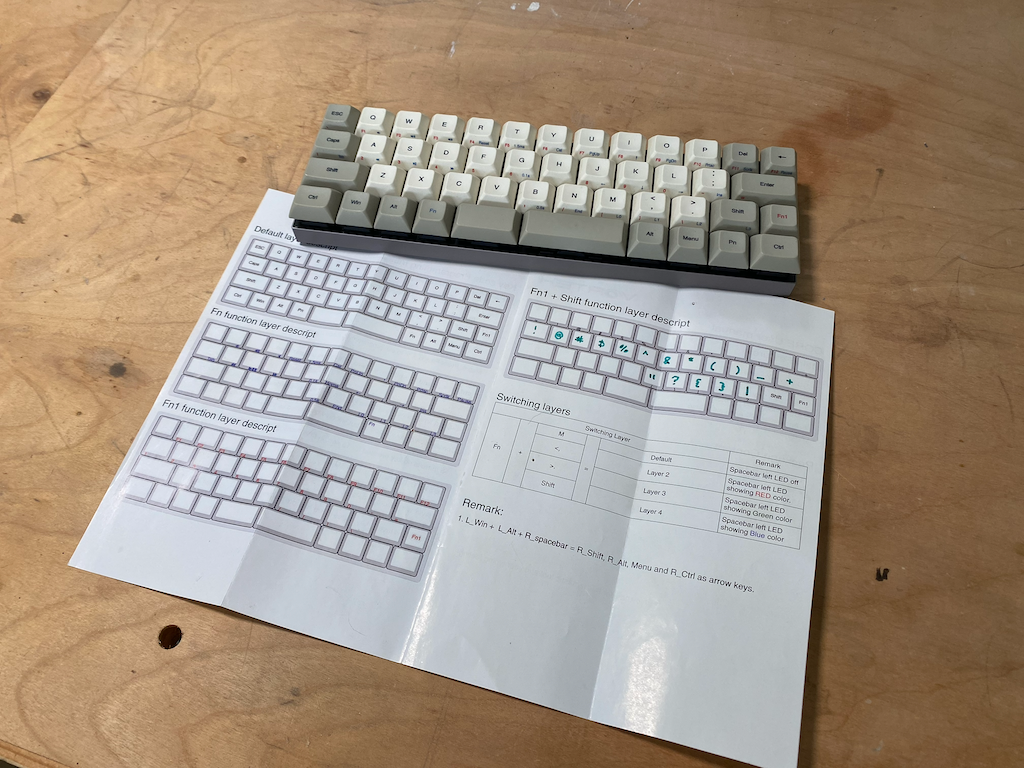
I dedicated myself to learning how to use it, daily driving it at work for two years. In the end I threw in the towel. Here were the key problems with the Core.
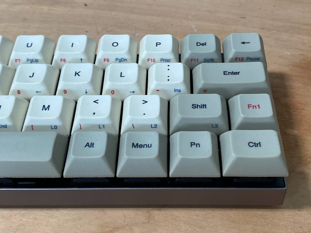
- An absolutely diabolical keymap. It took a three key combination to type a question mark.
- No ability to remap (at the time).
But it did have some flashes of brilliance:
- Split spacebar.
- Dye sublimation on the sides of the keycaps showing the characters of various layers (a lot of them were missing or simply incorrect, but they were there!). To this day I know of no other keyboard that does this.
The thing that was truly brilliant about this board, and all 40% boards, is the ability to access keys like directional arrows without taking your hands off of "center", by adding additional layers. In theory this is much more efficient. I had just run into a poor implementation.
I took that lesson and built a custom 60% board with a split spacebar. I used iterations of that design in all my boards going forward.
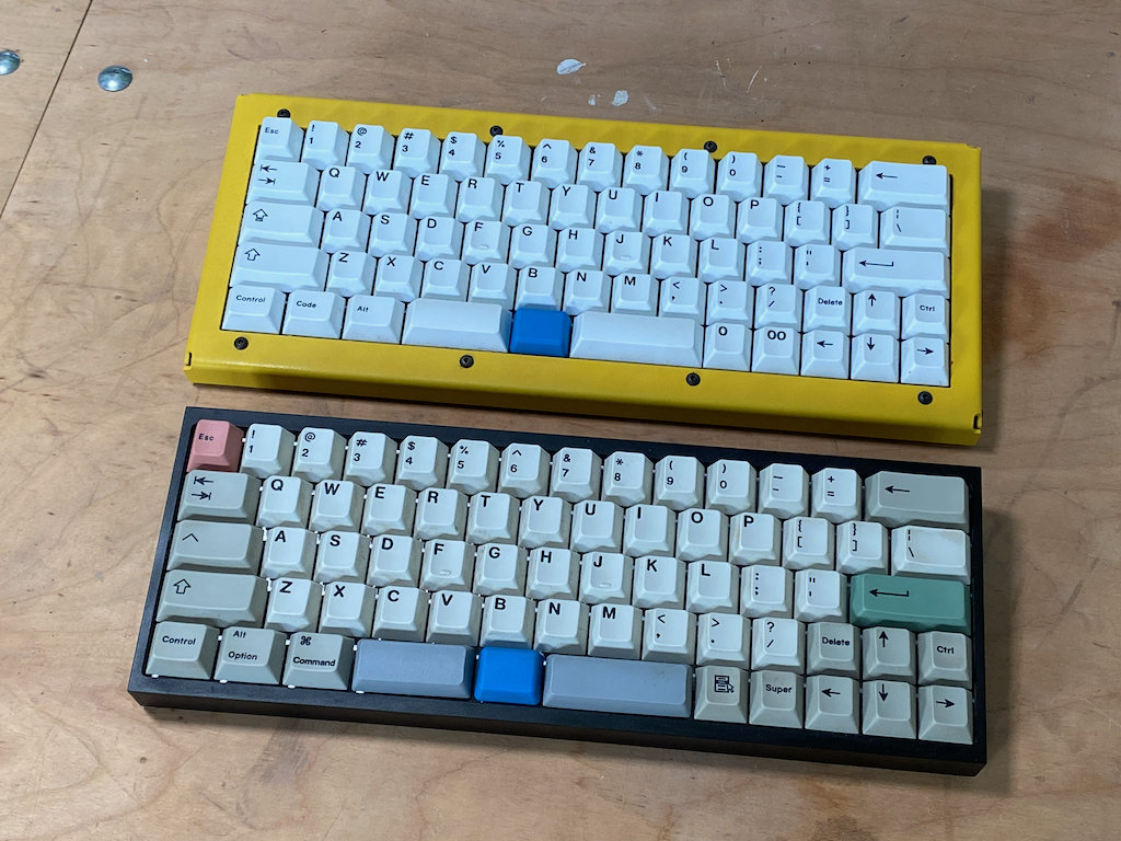
In the boards pictured above when you press the blue button you get arrow keys under your left hand and numbers under your right hand. A step in the right direction.
I could never get that 40% form factor out of my head though. In theory, it is better and more efficient if implemented properly...
Ortholinear
Ortholinear is when all the keys are aligned in a grid instead of being offset horizontally. The reason standard keyboards are offset that way is actually a remnant of mechanical typewriters and serves no practical purpose in a modern keyboard besides familiarity.
I have a strong reason to discard that familiarity though. One of the really amazing things about the design above is that when you push the blue button you get a full numpad under your right hand and arrow keys under your left hand, which makes it incredibly efficient to manipulate spreadsheets and more. The only issue however is that all numpads are ortholinear. It's the only part of a standard keyboard that follows this pattern. So when you try to operate a numpad with offset keys it just doesn't work right.
By adjusting the entire keyboard to ortholinear we get a full real standard numpad under our right hand without shifting off center.
Why No COLEMAK or DVORAK?
COLEMAK and DVORAK enthusiasts will have read the paragraph above about remnants of mechanical typewriters and thought to themselves 'QWERTY is also a remnant of mechanical typewriters, why did you keep that?'. That is a fair question. The answer is that it's already an adjustment switching to ortholinear and having all the symbols be in different places. After I've become completely familiar with this new layout maybe I will try them someday. I just decided it was too many things at once. Apologies!
Screen and Microcontroller On Back
Screens on keyboards might seem silly, but they are actually incredibly useful. They can display the status of your battery. Make it easy to change settings like OS or connection type, etc. But having a screen on the front of the keyboard does not appeal to me because it's a distraction. I don't want LED's on my keyboards either (or anything else really). By putting the screen on the back we can view and manipulate settings (and other things) without having a flashy distraction in our face.
If we also place the microcontroller on the back of the board we can keep a clean symmetrical profile with the smallest possible footprint.
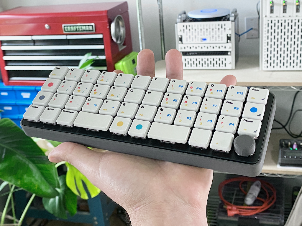
Low Profile Switches
This is a downstream consequence of putting the screen and microcontroller on the back. Without them the board would simply be too tall.
Alps RKJX Switch
The inclusion of the Alps RKJXT1F42001 switch in this project was definitely my Icarus flying too close to the sun moment. It's a rotary encoder and multi-directional switch in one, in a footprint that is actually compatible with a keyboard.
I'll be honest, I just thought it was cool. I can't believe it's not in common use in more keyboard projects.
Integrating this made the project much more complicated. This is definitely not a low profile switch and needed to be placed on a completely different PCB layer than the rest of the switches, meaning that the switch matrix actually spans two separate PCBs. It greatly complicates the project. Miraculously it worked in the end.
Microcontroller Selection
In short I picked the ESP32 S3 because it has Wifi. All the most popular microcontrollers for keyboards do USB and maybe Bluetooth, but none of them do Wifi. And that's a shame because Bluetooth is clunky and slow compared to something like the ESP-NOW wifi based protocol that lets ESP32s communicate with each other. It's 10x faster than Bluetooth and gives me the option to create an ESP32 based dongle so that I don't even have to negotiate a connection.
Then on top of that I can do crazy stuff like transmit a wifi network from my keyboard that my computer can connect to, and that network hosts a website where I can configure settings for the keyboard, like the keymap for example. Or I could turn it into a hacking tool. There are endless possibilities that open up with these more advanced microcontrollers.
The major downside is that none of the established keyboard firmware are compatible with them. For most people that is simply the end of the road. Who in their right mind would write a keyboard firmware from scratch!
Open Source Dev Board
I've open sourced the design files for the dev version of this board here:
GitHub: ncoughlin/ground-control-40-dev-board
If you are interested in building your own version of this board that will be a good starting point for you.
Comments
Recent Work
Basalt
basalt.softwareFree desktop AI Chat client, designed for developers and businesses. Unlocks advanced model settings only available in the API. Includes quality of life features like custom syntax highlighting.
BidBear
bidbear.ioBidbear is a report automation tool. It downloads Amazon Seller and Advertising reports, daily, to a private database. It then merges and formats the data into beautiful, on demand, exportable performance reports.